POWERMAG is the authorized sales and service for Yaskawa Drive, YASKAWA AC Drives, YASKAWA Servo Motor Drives and Motion Controllers
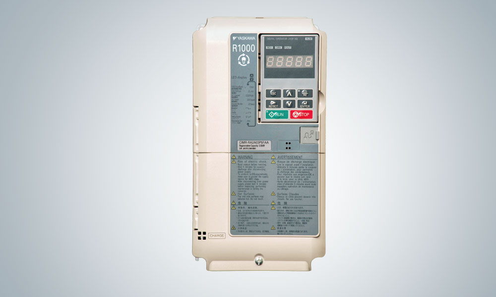
High Performance Vector Control Drive R1000
The R1000 is a power regenerative unit with both braking and regenerative functions. The R1000 shows great energy-saving performance in combination with an inverter. The R1000 will dramatically affect applications with large regenerative loads such as cranes and elevators.Because the R1000 does not require a braking resistor unit, it requires less space and enhances braking ability.
Ratings
- 3 ~ 200V, 3.5kW to 105kW
- 3 ~ 400V, 3.5kW to 300kW
Features
- Energy Saving Unit which helps in reducing operational charges
- Increased Braking Torque provides more braking power with continous regenerative operation.
- Reliable and Long life
- Preventive Maintenance.
- Easy support from a PC.
- Global Business Support.
Applications
- Crane
- Elevators & Escalators
- Centrifugal Seperators
- Winders
- Mixers
- Machine tools
Energy Saving Unit - 200V Class
| R1000 Model No | Preg(kW) | IDC(A) | IAC(A) |
|---|---|---|---|
| CIMR-RD2A03P5 | 3.5 | 14 | 10 |
| CIMR-RD2A0005 | 5 | 20 | 15 |
| CIMR-RD2A0007 | 7 | 27 | 20 |
| CIMR-RD2A0010 | 10 | 41 | 30 |
| CIMR-RD2A0014 | 14 | 55 | 41 |
| CIMR-RD2A0017 | 17 | 68 | 50 |
| CIMR-RD2A0020 | 20 | 81 | 60 |
| CIMR-RD2A0028 | 28 | 112 | 83 |
| CIMR-RD2A0035 | 35 | 138 | 102 |
| CIMR-RD2A0053 | 53 | 207 | 153 |
| CIMR-RD2A0073 | 73 | 282 | 209 |
| CIMR-RD2A0105 | 105 | 413 | 306 |
Energy Saving Unit - 400V Class
| R1000 Model No | Preg(kW) | IDC(A) | IAC(A) |
|---|---|---|---|
| CIMR-RD4A03P5 | 3.5 | 7 | 5 |
| CIMR-RD4A0005 | 5 | 11 | 8 |
| CIMR-RD4A0007 | 7 | 15 | 11 |
| CIMR-RD4A0010 | 10 | 22 | 16 |
| CIMR-RD4A0014 | 14 | 30 | 22 |
| CIMR-RD4A0017 | 17 | 36 | 27 |
| CIMR-RD4A0020 | 20 | 43 | 32 |
| CIMR-RD4A0028 | 28 | 58 | 43 |
| CIMR-RD4A0035 | 35 | 73 | 54 |
| CIMR-RD4A0043 | 43 | 89 | 66 |
| CIMR-RD4A0053 | 53 | 109 | 81 |
| CIMR-RD4A0073 | 73 | 149 | 110 |
| CIMR-RD4A0105 | 105 | 217 | 161 |
| CIMR-RD4A0150 | 150 | 320 | 237 |
| CIMR-RD4A0210 | 210 | 440 | 326 |
| CIMR-RD4A0300 | 300 | 629 | 466 |
| Control Characteristics | |
| Product | R1000 |
| Type | Power Regenerative Unit |
| Compatible Inverter Types | A1000, V1000, J1000, GA700, GA500, G7, L1000A, Servo Drives & All conventional Inverters (with a DC Bus), |
| Control Method | 120° excitation method |
| Regenerative Torque |
150% 30 s, 100% 25% ED 60 s, 80% continuous |
| Input Power Factor | 0.9 min. (for rated load) |
| Environmental Factors | |
| Ambient Temperature | −10 to +40°C (UL Type1), −10 to +50°C (IP00, IP20) |
| Altitude | Up to 1000 meters (derating required at altitudes from 1000 to 3000 m) |
| Humidity | 95% RH or less (no condensation) |
| Shock | (2A03P5 to 2A0053, 4A03P5 to 4A0073)10 to 20 Hz:9.8 m/s2,20 to 55 Hz :5.9 m/s2 (2A0073 to 2A0105, 4A0105 to 4A0300)10 to 20 Hz:9.8 m/s2,20 to 55 Hz: 2.0 m/s2 |
| Area of Use | Indoors (Protected from corrosive gases and dust) |
| Protection Features | |
| Fuse burnout | Operation stops if the fuse burns out. |
| Momentary Overcurrent Protection |
Operation stops for approx. 250% or higher of the rated power supply current. |
| Overload Protection | 30 s at approx. 150% of rated current. |
| Overvoltage Protection | 200 V class: Stops when input voltage exceeds approx. 227 Vac, Output:Stops when DC bus voltage exceeds approx. 410 Vdc 400 V class: Stops when input voltage exceeds approx. 554 Vac, Output :Stops when DC bus voltage exceeds approx. 820 Vdc |
| Undervoltage Protection | 200 V class: Stops when input voltage falls below approx. 150 Vac, Output: Stops when DC bus voltage falls below approx. 190 Vdc 400 V class: Stops when input voltage falls below approx. 300 Vac, Output: Stops when DC bus voltage falls below approx. 380 Vdc |
| Momentary Power Loss | Immediately stops after Momentary Power Loss is detected. |
| Heatsink Overheat Protection |
Thermistor |
| Charge LED | Charge LED illuminates when DC bus voltage is more than 50 V. |
| Standards Compliance | UL508C, IEC/EN61800-5-1, IEC/EN61800-3 |
| Power Specifications | |
| Rated input Voltage/Frequency | 400V Class: Three-phase AC power supply: 380 to 480 Vac 50/60 Hz 200V Class : Three-phase AC power supply: 200 to 240Vac 50/60Hz |
| Allowable Voltage Fluctuation |
−15% to 10% |
| Allowable Frequency Fluctuation |
±2% |
| Common Specifications | |
| Multi Function Digital Inputs | 8 Digital Inputs ( NPN or PNP ) |
| Multi Function Digital Outputs | 1 Programmable Relay M1-M2 (AC 250 V, max. 1 A DC 30 V, max. 1 A min. load DC 5 V, 10 mA), 1 fault relay MA-MB-MC(250 Vac, max. 1 A;30 Vdc, max 1 A(min. 5 Vdc, 10 mA)), 2 photcouplers P1,P2 (48 Vdc, max. 50 mA) |
| Multi Function Analog Output | 2 Multi function Analog outputs FM-AC & AM-AC (−10 to +10 Vdc ,2 mA) |
| Programming Interface | Serial port or USB B port in front of VFD |
| Serial communication | MEMOBUS/Modbus (RTU mode) comm. RS-485, Max. 115.2 kbps |
| Optional communication Protocols | Mechatrolink, CC-Link |
| Additional Functions | Cooling Fan on/off Switch, Removable Terminal Block with Parameter Backup, MEMOBUS/Modbus (RTUmode) Comm. (RS-422/RS-485 max, 115.2 kbps) |